In this article, we will discuss
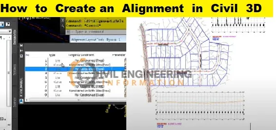
What is Alignment in Civil 3D | How to Create Alignment from Polyline | Visual appearance of Alignment | Calculation Super-elevation Alignment-based | Definition of Alignment?
What is Alignment in Civil 3D
Definition of Alignment
Alignments are a combination of lines, curves, and spirals viewed as one object. It is called Alignment.

Introduction
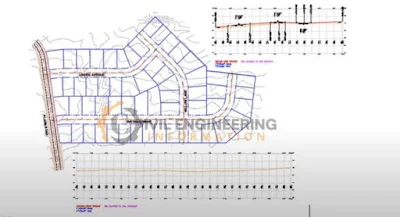
Alignment objects can stand for the middle of a road, a network of pipes, or any other construction baseline. One of the first steps in designing a road, a railroad, or a site is making and defining a horizontal alignment. You can draw the geometry of the alignment as a polyline and then use that geometry to make the named alignment. With the Alignment Layout Tools, you can make an alignment object that gives you more control. You can also change alignments by using grips or the commands on the Alignment Layout Tools toolbar. When you do this, the tangency between the alignment parts is automatically kept.Alignments can be objects on their own or the parent object of profiles, sections, and corridors. If you change an alignment, the changes are automatically made to any other objects that use that alignment.
Offset and curb return alignments can also work independently. Still, they are often dynamically linked to other alignments. As parts of an intersection, offset alignments and curb returns can be made automatically. Widenings can also use offsets.
Read More
Calculation Super-elevation Alignment-based
After you've made an alignment, you can figure out how the corridor goes around corners. You can figure out cant along rail alignments or superelevation along the centerline, offset, and curb return alignments.Alignments can be found in either the Alignments collection or the Site collection on the Prospector tab. From these collections, you can change how the alignment works, make reports, and send LandXML.
Note: In an Autodesk Civil 3D drawing, a user can set up as many alignments as they want.
Visual appearance of Alignment
Styles allow you to customise the visual appearance of alignment components and labels. You can create distinct styles for use in different stages of a project. When you create an alignment, you specify a style for the alignment object and styles for the alignment labels. You can create groups of styles for alignment labels in the Alignment Labels dialogue box and then save those labels as a label set to use with other alignments.How to Create an Alignment in Civil 3D
In this article, we will discuss creating alignments using the Pi method.Open AutoCAD Civil 3D
- First, let's navigate to the Home tab.
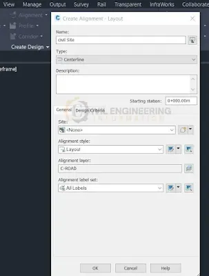
- Create the Design Panel Alignment Dropdown & click on Alignment Creation Tools.
- Give a name to your alignment and make sure the type is set to Centerline.
- Give it the style of layout, and make sure we have our labels set to all labels.

If this alignment needed design criteria, we would turn it on here and come up with some kind of starting design speed. Design criteria are how you can use Ashton methods on your road, as well as the design check sets, like checking for tangent lengths and curve checks. At the moment, we'll turn this off and click OK. Then opens up the alignment Layout tools.
Let's click on this drop-down menu and see how we can set a default curve for our curves by going to the curve and spiral settings.

We'll keep it at 200 for now and talk about how to change the curves. After that, click OK, and let's click on the Tangent to get started. Use the curves tool to make a tangent.
We'll use the transparent commands for this alignment because we already know some of the distances and coordinates.
First, let's go to the northern, eastern one by typing "'E" for northern eastern.
At the prompt, let's type 901-285-0932 for the Northern and press Enter. Type 145-64-1465 for the Easting and then press Enter. This begins to line up at that Northern Easting. Press Escape to stop the transparent command.
Notice how we're using rubber bands to keep the alignment going. You can use the circles to set the additional PiS. Let's use the Center Snap to connect to them. Take note of how the default radius is being used. We want to connect to an existing Roadway Centerline with a known Northern Easting. So we'll type Apostrophe Ne again and then hit the Enter key. Now, let's type in the Northern coordinates for 90204: 6.977,624, press Enter, and then type in the Easting coordinates for 145464: 7.923,116, press Enter. Now that we're there, press Escape once to return to the command. Now, we know the direction and distance to the end of the alignment, which matches our existing centre line.

civil 3d polyline crossing in profile
With Civil 3D 2022, it is now much easier to see and label crossing elements in profile views in a dynamic way.
To show crossing elements, select a profile view and choose "Add Crossings to Profile View" from the contextual ribbon. Then you can choose the entities you want. (Feature Lines, Survey Figures, 3D Polylines, Alignments, and Profiles are all supported entities.) Crossings are shown with a style of marker and label that automatically updates when changes are made to the linear elements they belong to.

How to Create alignment from polyline
To make an alignment from that polyline, click Alignment > Create Alignment from Objects in the Create Design panel on the Home tab of the ribbon. The command line tells you to choose a line, an arc, a polyline, or an object that is a line, an arc, or a polyline inside of an Xref.Read More
conclusion
Full article on What is Alignment in Civil 3D | How to Create Alignment from Polyline | Visual appearance of Alignment | Calculation Super-elevation Alignment-based | Definition of Alignment? | how to make a road profile in AutoCAD Thank you for reading this article in its entirety on the "Civil Engineering Information" platform in English. If you found this post useful, please share it on social media. If any BBS formula is missing from this article, please let me know in the comments.

